Validynamics > Motor Comprehensive Performance Testing System
It is an advanced system developed by the internationally leading Validynamic team, designed to perform motor performance tests using a dynamometer load. This system can be used for testing the comprehensive characteristics of motors and drivers, including those for new energy vehicles, servo robots, brushless motors, and other various types of motors and drive systems.
The system is characterized by flexibility in use, precise and stable testing, and safe and convenient operation. It also boasts a wide testing range and powerful analysis functions. This makes it widely applicable in various industries, including motor research and development, testing, quality certification, and selection in fields such as aerospace, aviation, defense, civil applications, universities, research institutions, and robotic servos.
Motor Comprehensive Performance Testing System
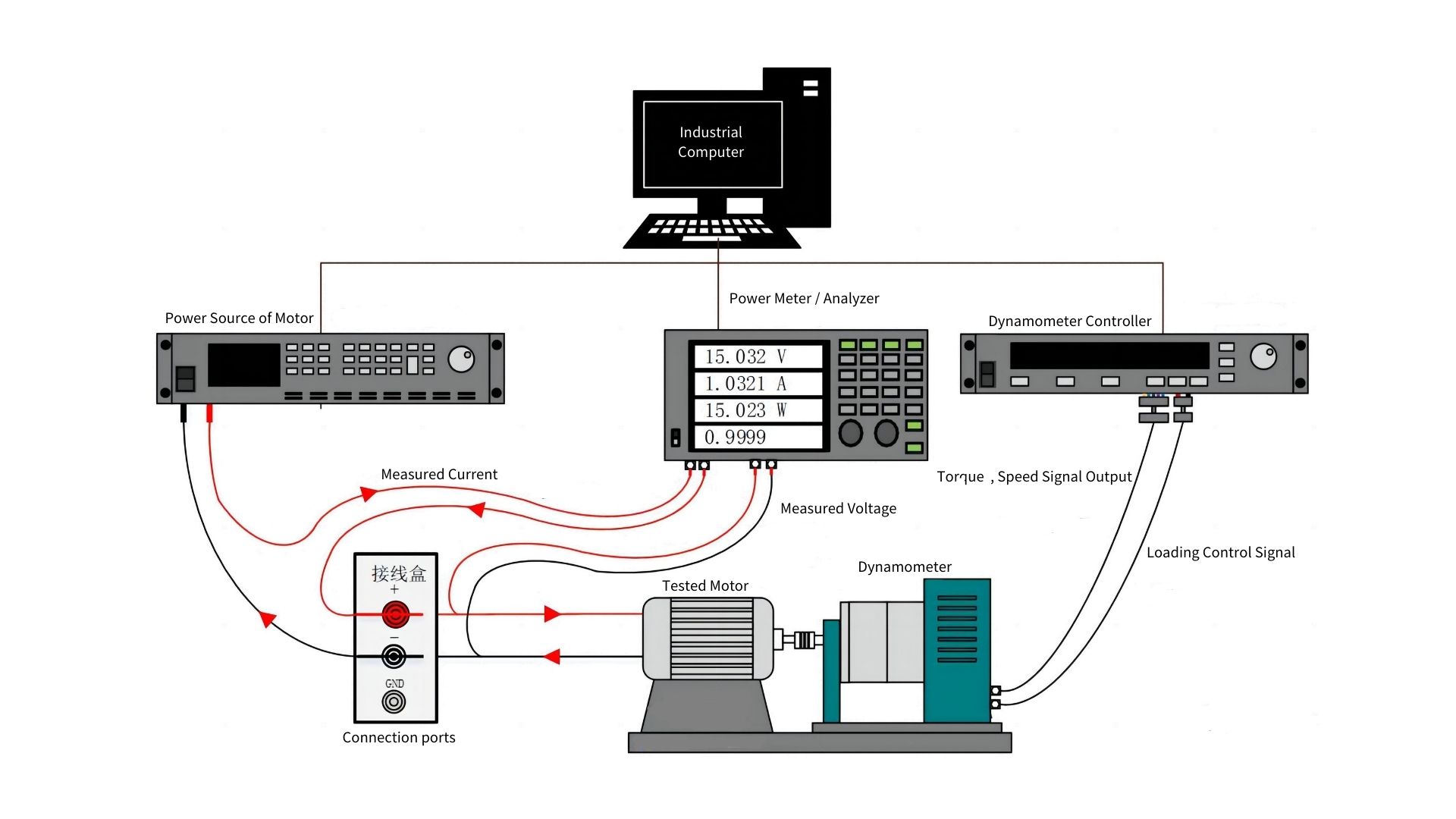
This system is an advanced testing device capable of data acquisition and simulation of various operating conditions under the Windows 7/10 operating system. It consists of components such as the dynamometer, dynamometer controller, power analyzer, and power supply for the tested motor. The dynamometer control system uses the host computer testing software as the core, which communicates with the dynamometer for load control and collects mechanical signals (torque, speed, direction, output power). It also communicates with the power analyzer to read electrical parameters (bus voltage, bus current, input power, UVW voltage, UVW current, etc.). The control computer is responsible for controlling the test system, interlocking, operating, and fault diagnosis. Data is processed via Ethernet, with the control computer’s output sent to a data processing computer for analysis.
Load Performance Testing System Overview:
The load performance testing system for both brushed and brushless motors follows the same basic principle: it uses a dynamometer (or test rig) to apply load and simulate the motor’s performance under various operating conditions.
Components of the System:
Dynamometer (Dynamometer with Torque and Speed Sensors):
This component is responsible for applying the load to the motor being tested. It is integrated with torque and speed sensors to accurately measure motor output under various load conditions.
Load Controller:
This device controls the application of the load to the motor, allowing precise adjustments based on test specifications. The load can be varied in real-time during the test to simulate different operating conditions.
Electrical Parameter Instrument (Power Analyzer):
Used to measure critical electrical parameters such as input voltage, current, power, and efficiency during the test. It ensures that the motor’s electrical performance is monitored and recorded accurately.
Industrial Computer (IPC):
The IPC serves as the control center for the test system, running the test software, managing communications between components, and logging test data.
Motor Power Supply:
Supplies the necessary power to the motor under test. The supply voltage is adjusted to match the motor’s rated input voltage, ensuring the motor operates under the correct conditions.
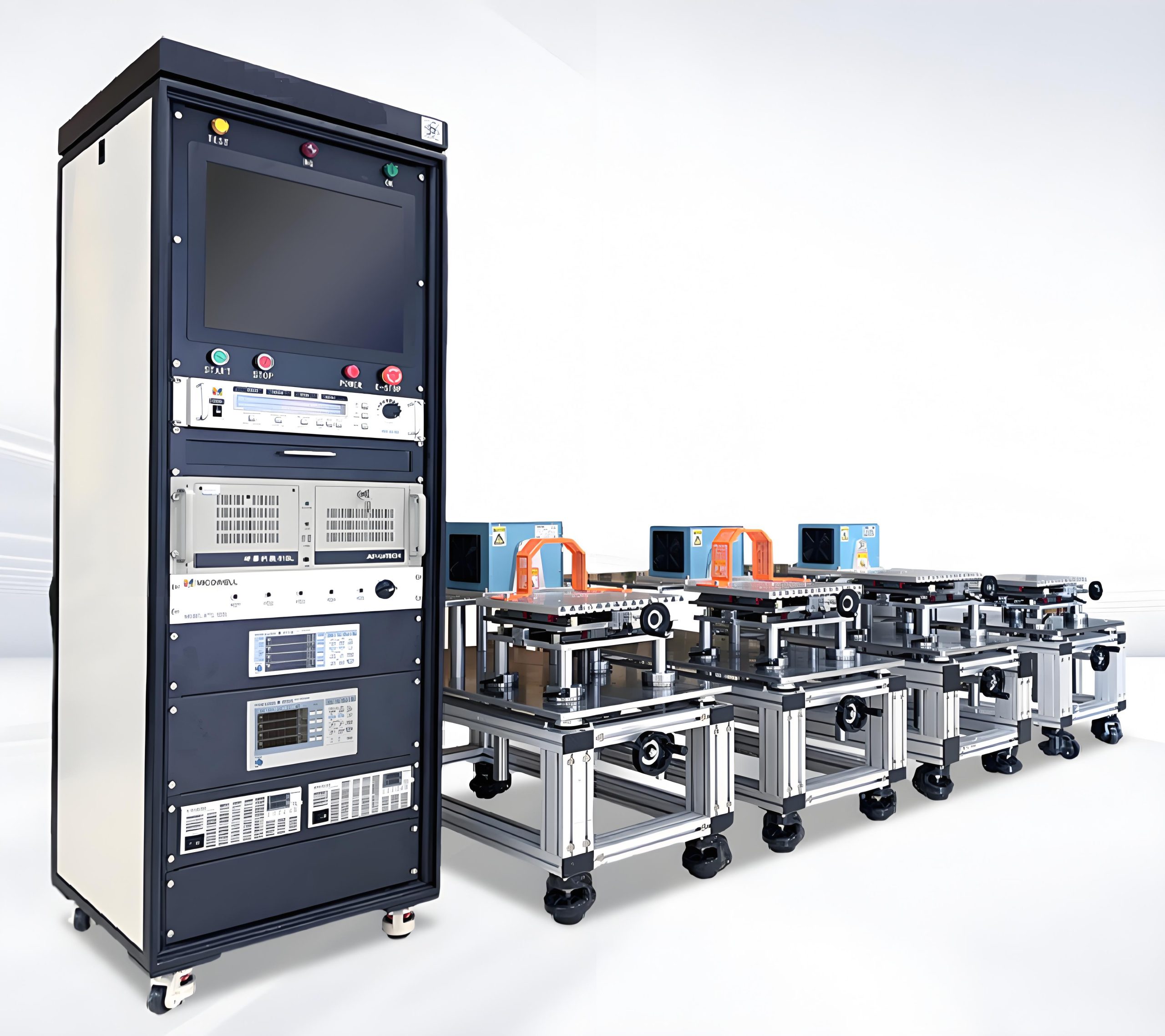
Test Cabinet:
Houses the various system components, providing an organized space for all necessary devices to be housed and ensuring safety and ease of access during the test.
Test Frame/Stand:
Supports the motor and dynamometer securely, ensuring proper alignment and stability during testing. This structure also accommodates various mounting fixtures and components.
Fixtures and Clamps (Jigs):
These are used to hold the motor and components in place during testing. They ensure that the motor is securely mounted, minimizing vibration or misalignment during the load performance test.
Test Software:
The software is responsible for controlling the test procedure, monitoring parameters, and collecting data. It allows users to set testing criteria, analyze results, and generate performance reports. This software is often capable of automating the load application and data collection process, making testing efficient and repeatable.
Working Principle: The basic working principle of the system is to load the motor under test using the dynamometer. The test system adjusts the load in accordance with the test parameters (such as torque, speed, and time), while continuously measuring both the electrical and mechanical performance of the motor. The test software ensures that all parameters are recorded, analyzed, and used to generate accurate performance data.
The system can simulate real-world operating conditions and test the motor under different loading scenarios, such as varying speeds and torque, to assess the motor’s performance, efficiency, and other key characteristics like heat generation, stability, and response to dynamic load changes.
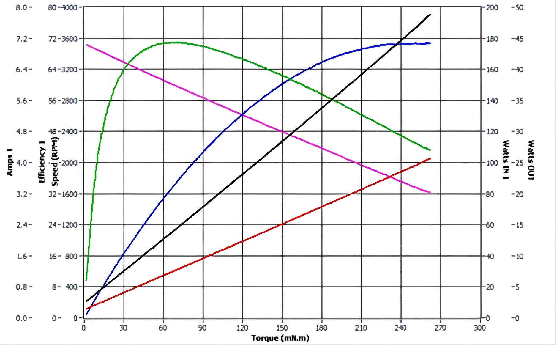
Torque-Speed Characteristics:
The torque-speed curve is automatically tested and plotted by the industrial control computer software. The measurement of drive motor, drive controller, and system efficiency mainly relies on a high-precision power analyzer and dynamometer. The system automatically measures and provides results in report form.
Full Automatic Testing:
Test Objective: To draw the torque-speed relationship curve within the motor’s operating range.
Testing Method: The dynamometer is used as the load for the motor under test, and the motor is kept in a heated working state. The DC bus voltage of the motor controller is set to the rated voltage, and the maximum working current is configured. During the experiment, the dynamometer software adjusts the optimal PID values based on the set speed limits and descent speed, automatically applying the load within the set speed range to generate the characteristic curve.
This testing system provides precise and reliable data, making it suitable for comprehensive motor performance analysis across a wide range of industries.
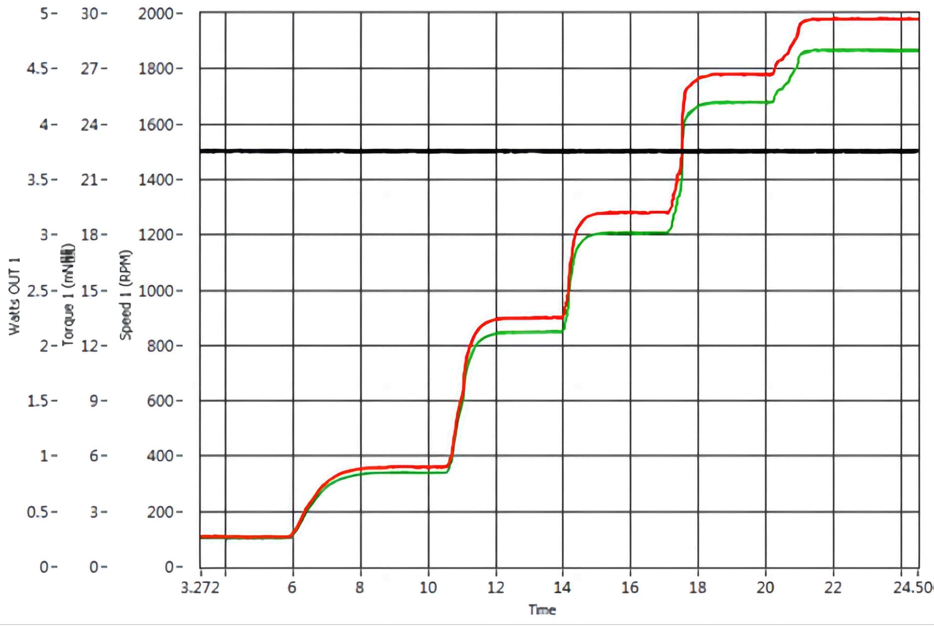
Constant Speed or Constant Torque Testing
Test Objective: The purpose of the test is to apply a series of specified speed or torque points for loading control, allowing the observation of the motor’s performance under specified operating conditions.
Testing Method:
Load Setup: The dynamometer is used as the load for the motor under test, ensuring that the motor is in a heated working state.
DC Bus Voltage Setup: The DC bus voltage of the motor controller is set to the rated voltage, and the maximum operating current is established.
Test Execution: During the test, the dynamometer software automatically applies the load according to the set speed or torque points, adjusting the optimal PID values.
Automatic Control: The software allows the motor to operate at specified speed or torque points based on user-defined loading steps. The test results are used to automatically generate characteristic curves for the motor.
This type of testing is used to analyze the motor’s performance at specific speed or torque values and is crucial for understanding how the motor behaves under different conditions.
Manual Loading Test
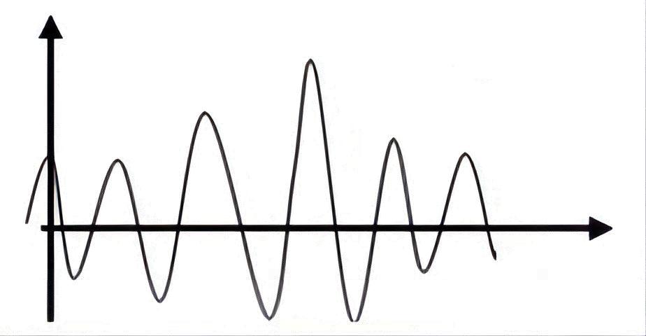
Test Overview: The manual loading test significantly reduces the PID adjustment time during closed-loop load loading. By using open-loop loading, this test allows for manual control, enabling dynamic loading of any load waveform. This provides users with a true simulation of the motor’s actual operating conditions.
Key Features:
Manual Control: The test allows for precise manual adjustment of the load, enabling the motor to be subjected to a variety of load profiles that reflect real-world operating scenarios.
Open-Loop Testing: Instead of relying on automated control loops, the test operates in an open-loop mode, offering flexibility in load application and simulation.
Dynamic Load Waveform: Users can apply custom load waveforms to simulate different operational conditions, providing insights into how the motor behaves under various load variations.
This test is particularly useful when a more specific or varied range of conditions is needed to simulate real-life scenarios or to identify motor performance under customized loading conditions.
Demo / Application Video
Motor Testing with Hysteresis Dynamometer BHD303 + M Test Software.