Stepper Motor Pull-In and Pull-Out Torque Measurement System
Validynamics > Stepper Motor Pull-In and Pull-Out Torque Measurement System
The Stepper Motor Pull-In and Pull-Out Torque Testing System is a cutting-edge, automated solution designed for precise measurement and analysis of stepper motor performance. Tailored for medium- and small-sized stepper motors, this system streamlines the testing of key torque characteristics, including pull-in torque, pull-out torque, holding torque, and detent torque, while also assessing stepping angles, frequency limits, and more. With one-click operation and real-time data recording, it eliminates the inefficiencies and inaccuracies of manual methods, providing reliable results and comprehensive performance curves with ease.
Stepper Motor Pull-In and Pull-Out Torque Measurement System
The testing methods for stepper motor pull-in torque and pull-out torque are clearly defined in the national standard GBT 20638-2006. Four specific methods are described:
Magnetic powder brake + torque sensor method,
Dynamometer testing method,
Rope and spring balance testing method,
Rope and dual spring balance testing method.
Each of these methods has its specific applicability:
The first two methods cannot test small-range stepper motors due to issues with rotational inertia.
The last two methods cannot test large-range stepper motors and are cumbersome, requiring manual data recording.
To address these challenges, our company has developed a testing system specifically designed for the pull-in and pull-out torque testing of medium- and small-sized stepper motors. This system enables one-click measurement, automatically outputs results and curves, and resolves the complexity of manual testing and errors caused by human data recording.
Key Features
The system is customized to meet customer needs and primarily automates the testing and recording of:
Maximum static torque (holding torque),
Detent torque (unpowered holding torque),
Output torque (torque-frequency characteristics),
Starting torque (pull-in torque),
Stepping angle and stepping angle error,
Maximum no-load start-up frequency and running frequency.
This customized testing system is essential to efficiently meet the testing requirements for stepper motors.
Test Parameters:
T: Torque of the motor under test T(mN.m)=(F1-F2)× (D1+D2)/2
F1: Force of the fixed sensor (N)
F2: Force of the movable sensor (N)
D1: Diameter of the pulley (mm)
D2: Diameter of the tensionless traction rope (mm)
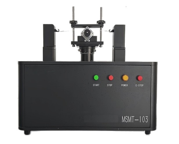
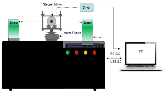
Composition and Functions:
The stepper motor pull-in/pull-out torque testing device consists of the following components:
Force sensors,
Fixture tools,
Single-axis robot,
Tensionless traction rope,
Pulleys,
High-precision magnetic encoders.
When testing, the stepper motor to be tested is securely fixed in place. A pulley (equipped with a planar magnet) is locked onto the motor’s output shaft, and the tensionless traction rope is wound around the pulley connected to the motor shaft. Both ends of the rope are hooked onto two force sensors.
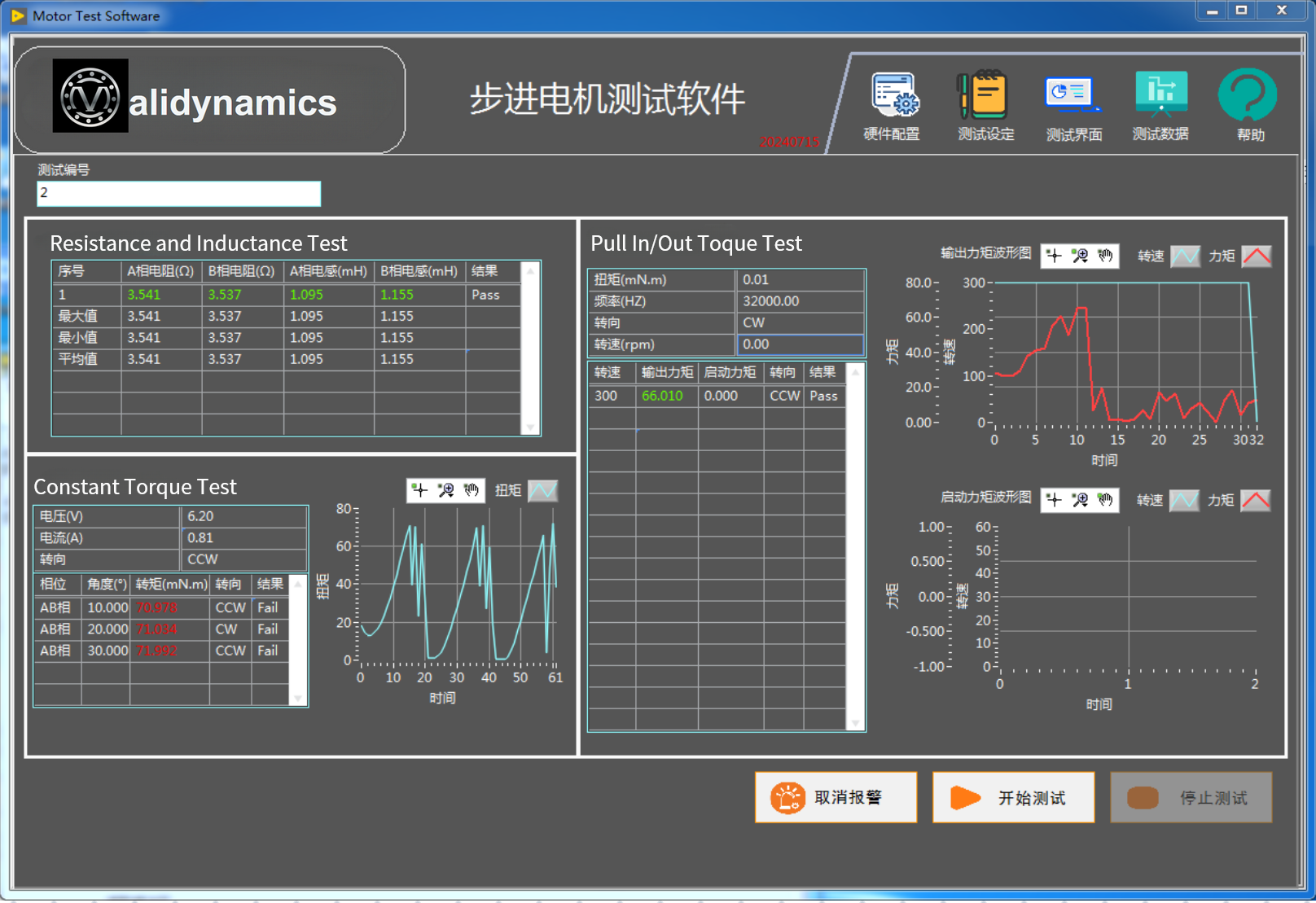
The software controls the tested motor to rotate while simultaneously controlling the movement of the sensors via a single-axis robot. Torque is applied to the motor through the pulley. The software records the real-time values from the two force sensors and the rotational speed of the magnetic encoder until the motor loses step synchronization. The torque is then calculated using a formula, with the maximum torque at that frequency segment being taken as the pull-out torque.
Using this approach, the system measures the pull-out torque across different frequencies (rotational speeds) and generates a curve illustrating the results.
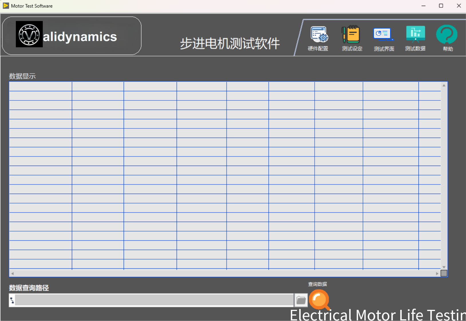
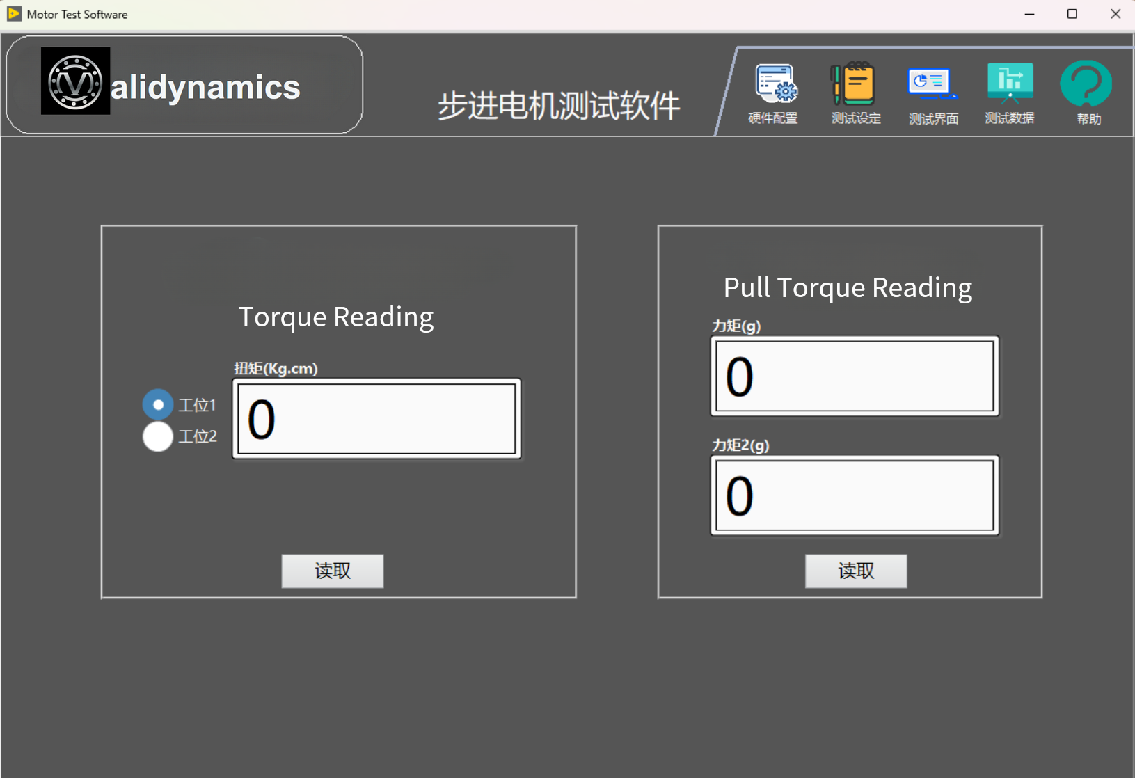
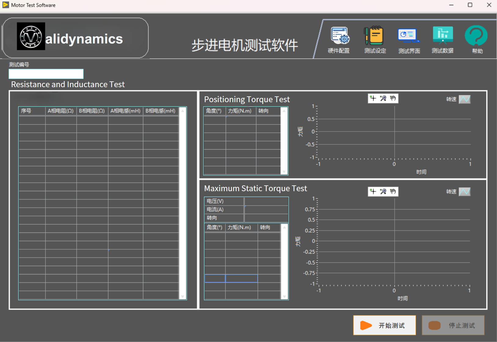
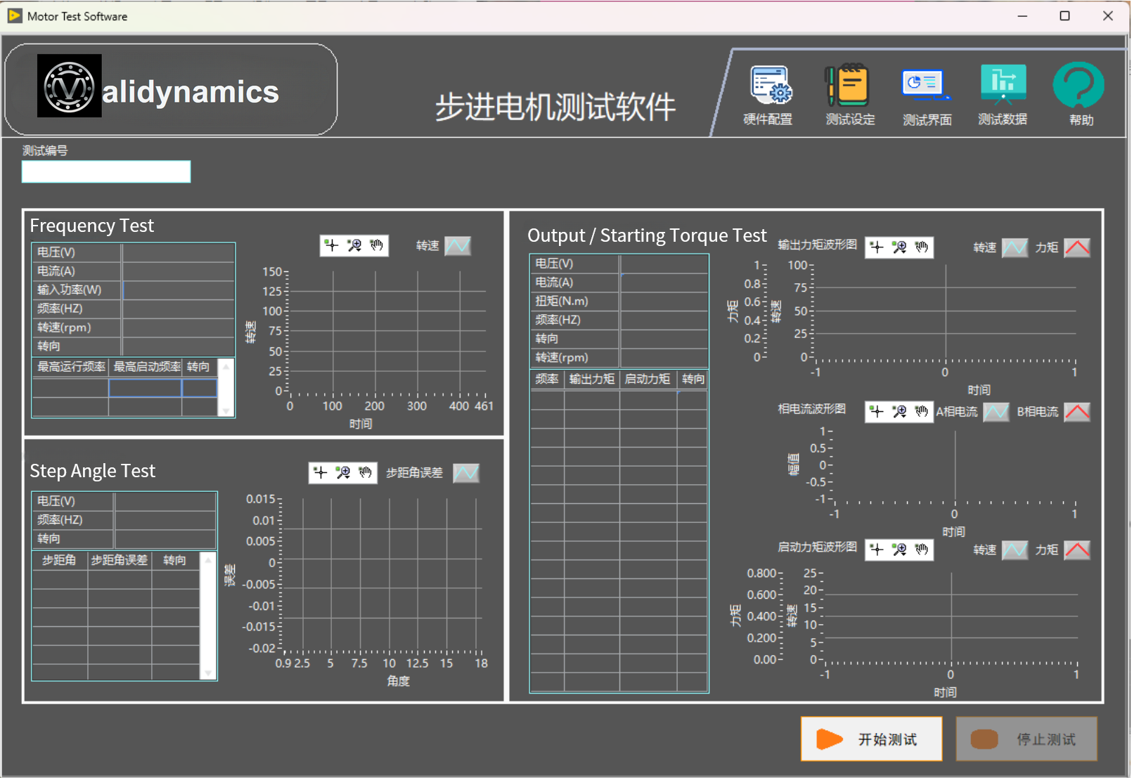
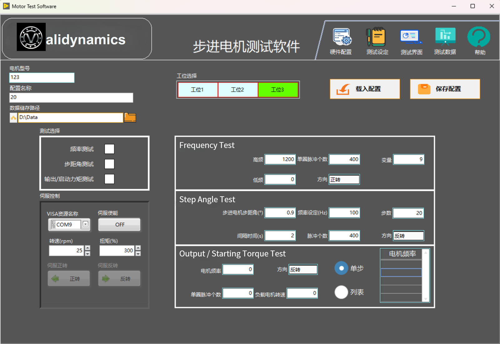
Software Interface:
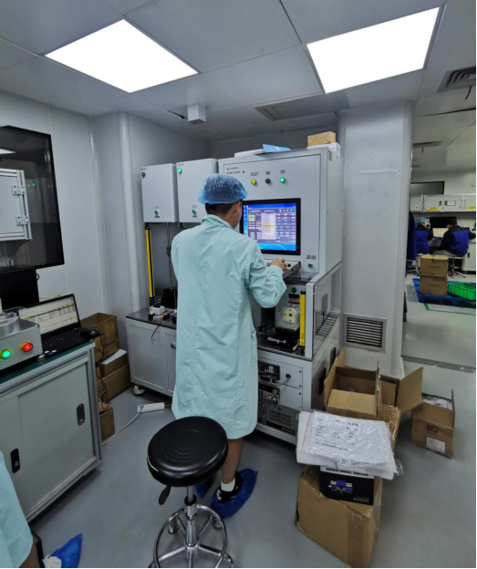
Demo / Application Photo
Application of Stepper Motor Pull-In and Pull-Out Torque Measurement System.