This system is designed for performance testing of household appliance compressor motors or known as “white goods” compressor motors.
The motor characteristic testing system is suitable for measuring single-phase and three-phase AC variable-frequency motors. It supports comprehensive testing, fixed-point testing, and manual testing to obtain various motor parameters, including torque, speed, output power, voltage, current, input power, power factor, rotation direction, and efficiency. It boasts high reliability and good repeatability. The testing range includes a maximum power of 30KW, maximum torque of 100N·m, maximum rotational speed of 25,000rpm, and a testing accuracy of ±0.5%.
The motor testing methods of this system strictly comply with relevant national standards. The standards involved in this solution are as follows:
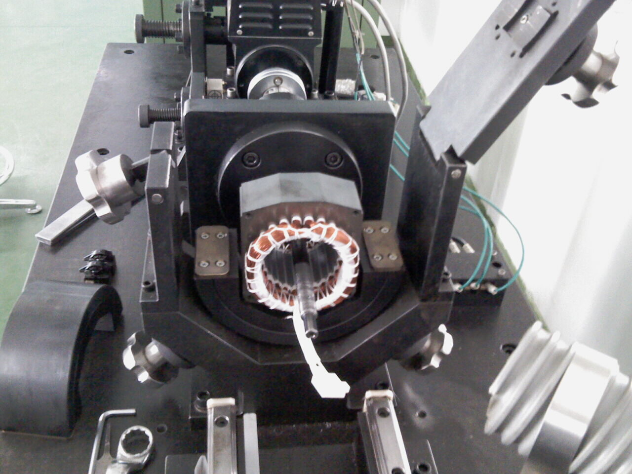
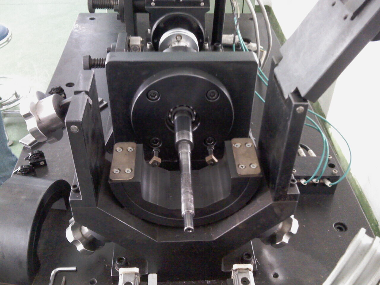
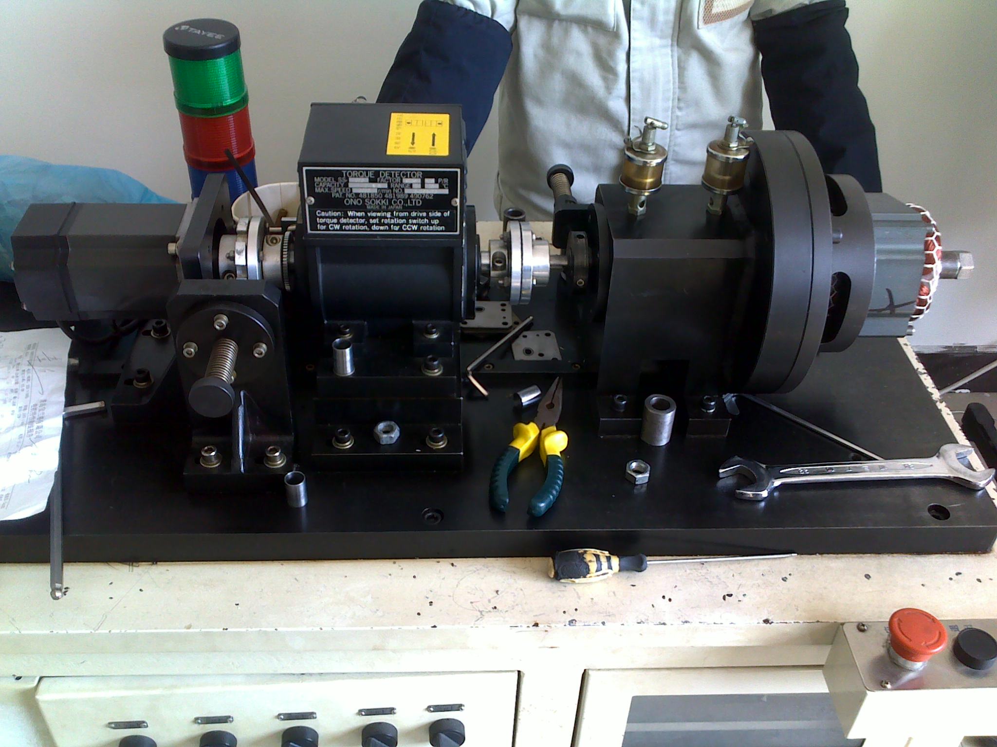
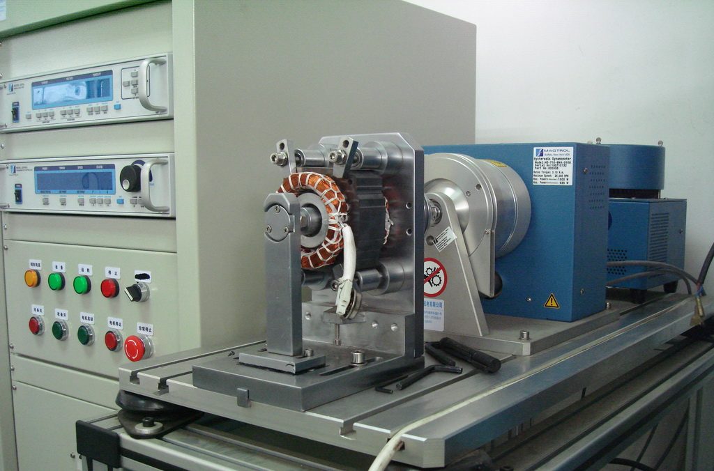
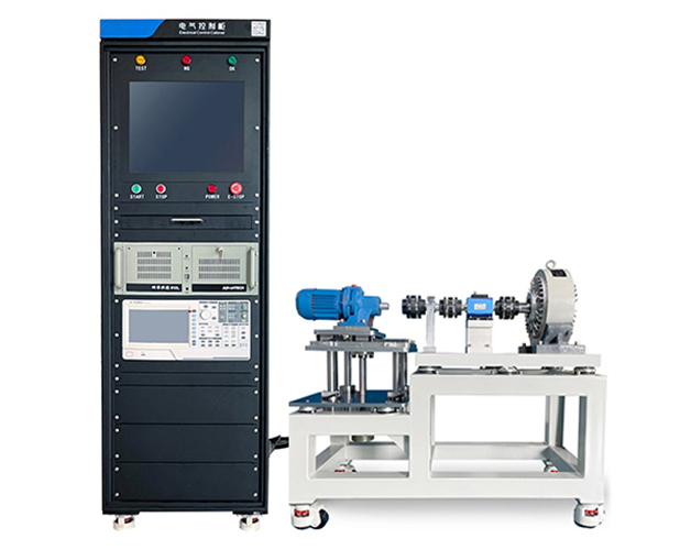
The test bench consists of the motor under test, drive system, dynamometer, and fixtures. The image below represents the standard vertical cabinet paired with a testing steel bench.
The motor testing functions include assessing the basic operational conditions of the motor. It can also simulate operational conditions at various speeds, enabling users to predict potential scenarios during actual applications. For instance, it can simulate motor operation under load or in a constant torque state, showing the corresponding changes between torque and speed.
Torque-speed curves are automatically tested and plotted by the software on the industrial control computer. Measurement of drive motors, drivers, and system efficiency mainly relies on high-precision power analyzers and imported dynamometers. Test results are automatically generated in report form. The methods and standards are detailed below:
This phase verifies whether the manufacturer’s specified parameters meet the requirements. By entering the continuous torque, continuous power, peak torque, and peak power into the industrial control computer’s software, the system automatically measures the results, evaluates compliance, and outputs a detailed report.
Pm — Continuous power at the shaft end of the drive motor, measured in kilowatts (kW).
Testing Purpose: To verify that the drive motor’s peak torque meets the specifications outlined in the product’s technical documentation.
Testing Method: Using the manufacturer’s provided reference for peak torque during operation (either 1 minute or 10 seconds of continuous operation), experiments are conducted for measurement. As a special case of peak torque, the maximum torque at each speed operating point can be tested. During the experiment, the testing duration at the maximum torque point can be very short, typically less than 10 seconds (this can be set through industrial control software). Based on the experimental data, a speed-to-maximum torque curve for the drive motor system is plotted.
Peak Torque Measurement:
Testing Purpose: To verify that the drive motor’s peak power meets the specifications outlined in the product’s technical documentation.
Testing Method: By obtaining the peak torque and the corresponding operating speed as described, the specified continuous power can be calculated using the following formula:
Pc= T x n / 9550
Pc — Peak power at the shaft end of the drive motor, measured in kilowatts (kW).
Testing Purpose: The locked-rotor test measures the locked-rotor current (IK) and locked-rotor torque (TK) at rated voltage. It also determines the relationship curves between locked-rotor current, locked-rotor torque, locked-rotor input power, and input voltage, collectively referred to as locked-rotor characteristic curves. By analyzing the magnitude and three-phase balance of the locked-rotor current, it reflects the rationality and quality of the motor’s stator and rotor windings, as well as the magnetic circuit formed by the stator and rotor. This provides actual test data for design and process improvement, as well as assistance in identifying failure causes and determining repair methods for malfunctioning motors.
Testing Standards:
GB/T 22669-2008 Test Methods for Three-Phase Permanent Magnet Synchronous Motors, Chapter 7: Locked-Rotor Testing
GB/T 1032-2012 Test Methods for Three-Phase Induction Motors, Chapter 9: Locked-Rotor Testing
Free curve loading significantly reduces the PID adjustment time during closed-loop load testing. Through open-loop loading and manual testing, it enables the dynamic loading of arbitrary load waveforms, providing users with a realistic simulation of motor operating conditions in actual scenarios.
Motor Testing System for Automotive Auxiliary