Motor Cogging Torque and Friction Torque Testing System
Validynamics > Motor Cogging Torque and Friction Torque Testing System
A cogging torque testing system is an independent testing system used to control and measure cogging torque and friction torque.
Motor Cogging Torque and Friction Torque Testing System
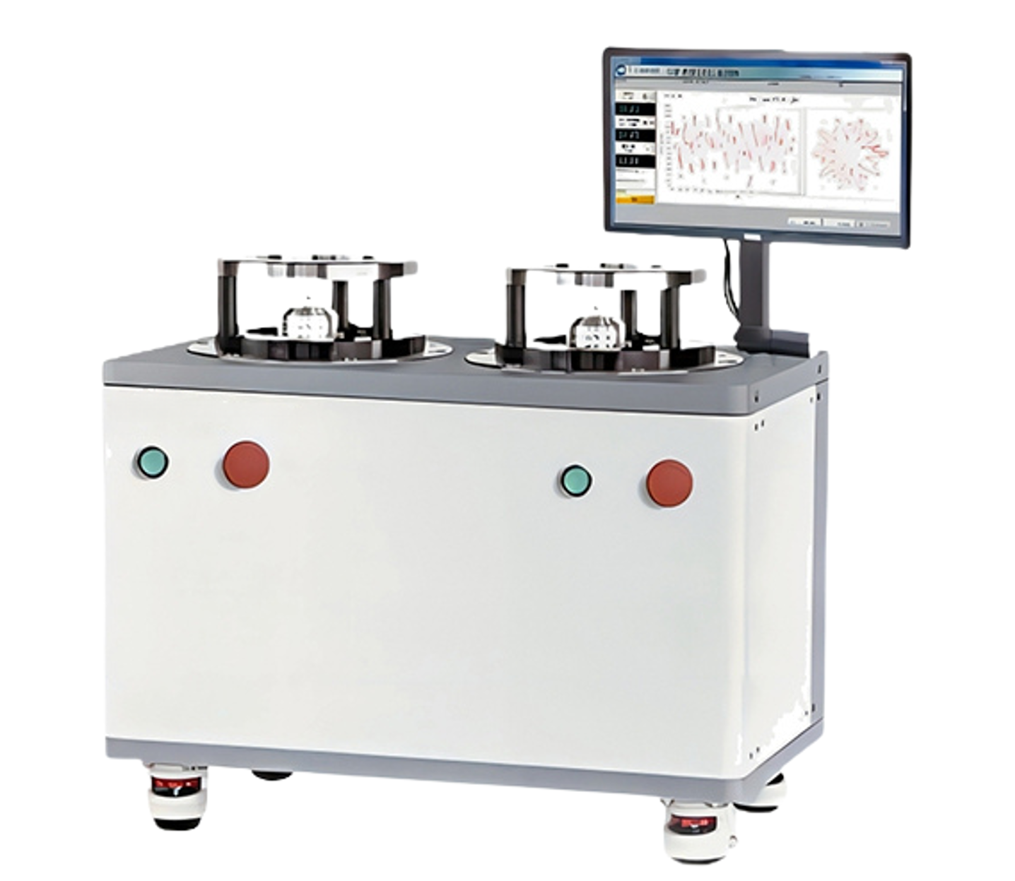
The Cogging Torque Testing System is a standalone testing solution designed to control and measure both cogging torque and friction torque. This system includes a precision reduction motor, a high-accuracy miniature torque sensor, and a built-in safety clutch to prevent overload due to improper use. The reduction motor drives the tested motor at low speeds, with selectable speeds ranging from 0.5 to 20 rpm, while simultaneously measuring the cogging torque related to the angular position.
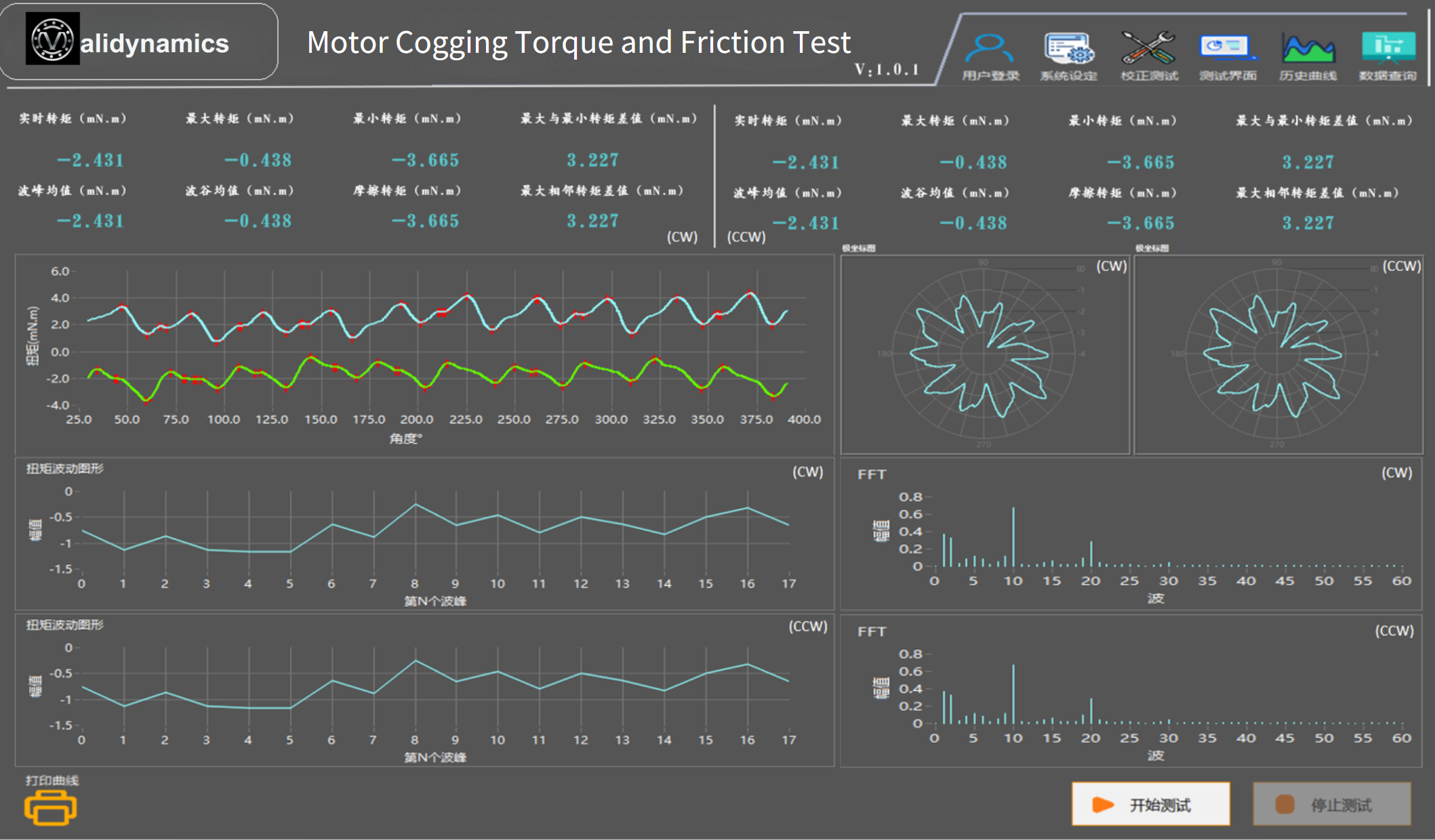
The standard model offers a maximum torque measurement range of 10 Nm (depending on the selected torque sensor’s range). The Windows-compatible executable software controls the system and displays the collected data. It provides accurate peak cogging torque measurements and displays angle-torque graphs or polar coordinate charts, along with FFT analysis. The software allows for the storage of measurement data and comparison of up to five performance graphs. Historical data can be loaded to generate cogging torque curves, and the start and end angles can be customized. Test process data can be saved as Excel files or TXT text files.
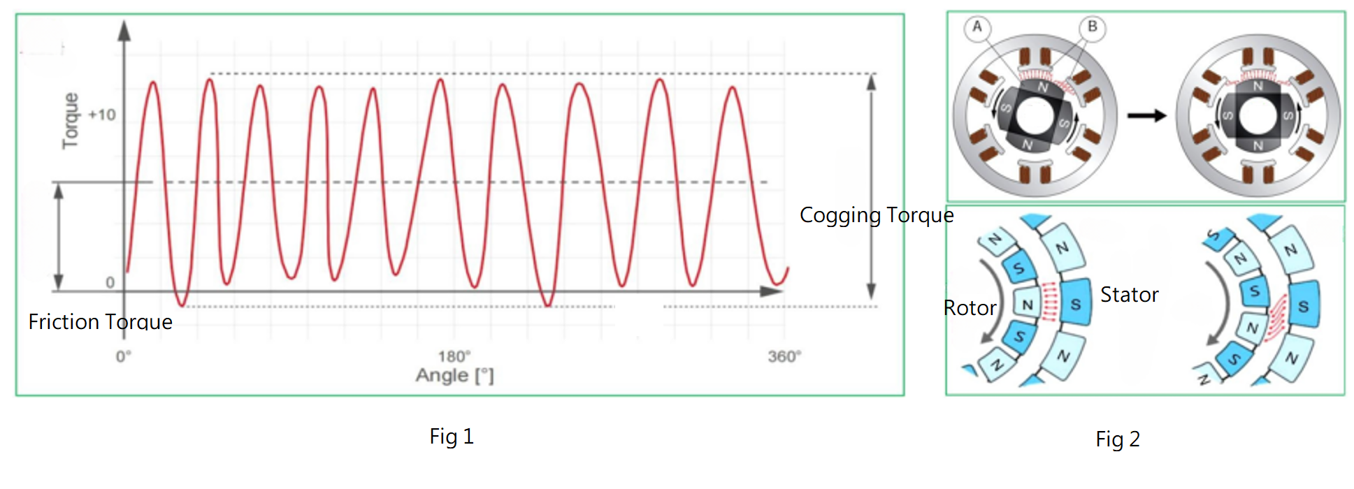
Fig 1: Typical cogging torque curve. The friction torque is the average cogging torque calculated relative to zero torque. The cogging torque is calculated based on the peak torque values.
Fig 2: When the magnetic poles N and S are facing each other (top left image), the attraction force is at its maximum. As the motor rotor rotates (top right image), before proceeding to the next movement, the moving magnetic element must first break free from the residual magnetism. This resistance to forward motion caused by magnetism is known as the cogging effect.
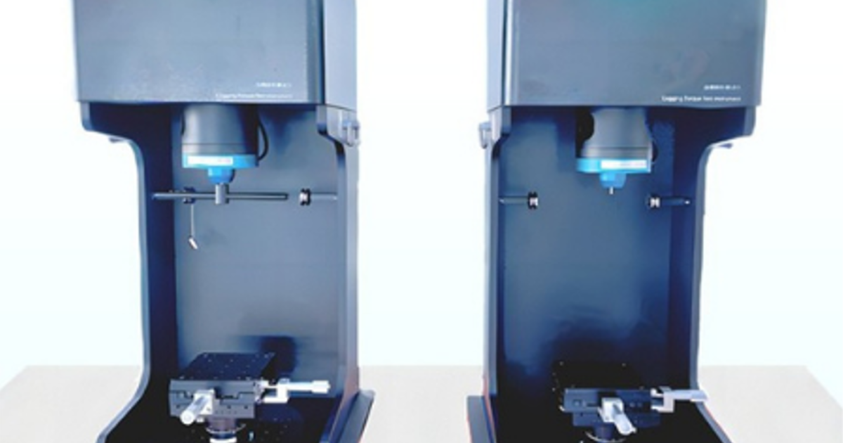
For enhanced precision and functional control, the software includes a motor position adjustment program for calibration (the test sample must not be connected to the system during calibration). As a standalone system, it only requires a 220-240V AC power supply. The USB interface allows for direct connection to a PC with the installed software. The system is mounted on a base plate with positioning holes, and motor fixtures can be installed onto this plate. A vertical mounting bracket is available for vertical installation, especially recommended for very low measurement values.
Validynamic’s cogging torque system software allows for customizable testing direction, whether CW, CCW, or bidirectional testing, all automated via the software. It can determine whether the motor passes or fails based on the preset upper and lower limits.
Cogging Torque and Its Importance in Modern Industry In modern industrial fields, motors are crucial driving components that play a vital role. Cogging torque is an important performance indicator of a motor, directly affecting its stability and noise levels. Traction torque or braking torque is an essential parameter in permanent magnet motors, particularly in permanent magnet servo motor systems. The braking torque of a permanent magnet motor consists of cogging torque and friction torque. Cogging torque is generated by the interaction of the motor’s magnetic poles with the teeth (steel structure) when the motor is not powered. It is one of the key parameters of permanent magnet motors and is a primary cause of torque ripple, vibration, and noise.
Typically, cogging torque varies with rotor position and is generally defined by its peak-to-peak (p-p) value. Friction torque, on the other hand, is attributed to mechanical assembly issues such as bearing resistance, assembly tolerances, or brush friction in permanent magnet DC motors (PMDC). Friction torque is usually measured by its average value.
Components of the Equipment
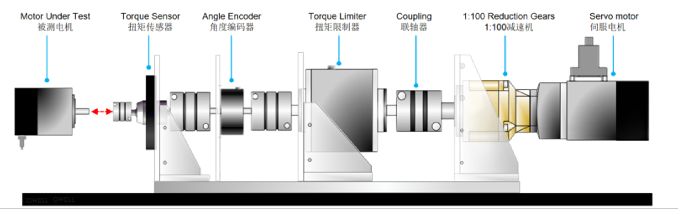
The cogging torque testing equipment developed by our team is designed for use after the prototype of the permanent magnet motor has been completed. The cogging torque test is crucial to verify the accuracy of the theoretical calculation method, the magnitude of any errors, and its validity. The standard cogging torque testing device is illustrated below. It consists of a driving motor that powers the permanent magnet motor rotor. A torque sensor and an angle encoder, mounted on the connecting shaft, are used to measure the torque and angle. The system can continuously measure the cogging torque at multiple rotor positions, providing torque-angle relationship curves and waveforms, among other data.
While small-scale micro-motor manufacturers often use manual methods to measure motor cogging torque, such methods are not within the scope of this introduction. The manual method typically involves fixing the motor stator onto a rotating platform, attaching a radial rod to the motor shaft, and applying weights at the end of the rod. By adjusting the weight, the torque corresponding to the horizontal position of the radial rod represents the cogging torque at that rotor position. By rotating the platform, the cogging torque at different rotor positions can be measured. However, we will not delve into this manual method here.
Model
Type
Torque Range
CTW-101
Horizontal
10 mN·m
CTW-501
Horizontal
50 mN·m
CTW-102
Horizontal
100 mN·m
CTW-502
Horizontal
500 mN·m
CTM-101
Vertical
10 mN·m
CTM-501
Vertical
50 mN·m
CTM-102
Vertical
100 mN·m
CTM-502
Vertical
500 mN·m
CTV-103
Vertical
1 N·m
CTV-503
Vertical
5 N·m
CTV-104
Vertical
10 N·m
Additional Information
Speed Range (r/min): Speed gears are 0.5, 1, 2, 3, 5, 10, 20 rpm