Validynamics > Multi-Station Motor Lifetime Testing Equipment
From our humble beginnings with a small hysteresis brake, we have grown to make it the core of our flagship products.
Multi-Station Motor Lifetime Testing Equipment
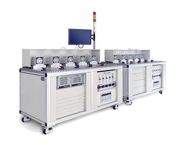
Equipment Overview
The motor lifetime testing equipment utilizes a braking system combined with an intelligent constant current source/servo motor + servo driver to form the testing system. The Motor Lifetime Testing System (ATC-1005) is an advanced solution that enables data collection through motor lifetime testing software, which operates under Windows 7/XP/10 operating systems.
Here’s the summarized description of the Motor Lifetime Test System (ATC-1005) and its components, with a focus on the working principle and software interface:
Motor Lifetime Test System (ATC-1005) Overview
Purpose: The system is designed for testing the lifetime of various types of motors, including AC/DC, servo motors, and other electric motors. The system allows for the monitoring and analysis of motor performance over extended periods, simulating real-world operating conditions.
Components:
Brake System: A key component in applying load during the test.
Intelligent Constant Current Source/Servo Motor + Servo Drive: These components help in controlling the motor’s operation during testing.
Motor Testing Power Supply (AC/DC): Provides the necessary power to the motor under test.
Industrial Control Computer: Controls the system and collects data.
Intelligent Controller: Regulates various test parameters.
Motor Testing Fixtures: Secure the motor during testing.
Test Software (MOTOR-TEST ATC-1006): Uses LABVIEW for data collection, graph plotting, and calculation of key parameters such as current.
Hysteresis Brakes: Used for braking and simulating load conditions.
System Block Diagram
The system can be divided into three major parts:
Data Acquisition:
Electrical Signals: Collected from the motor’s controller, including voltage, current, etc.
Mechanical Signals: Includes torque, speed, and other mechanical parameters from the motor.
These signals are measured with instruments and current transformers.
Control System:
Load Controller: Controls the load applied to the motor.
Brake System: Works in conjunction with torque and speed sensors for open-loop or closed-loop control of torque or speed.
Control Cabinet: Handles various hardware and software protections, such as overcurrent and over-temperature protection.
Auxiliary Components:
Based on actual testing needs, auxiliary components such as cooling systems, vibration sensors, and temperature sensors can be added.
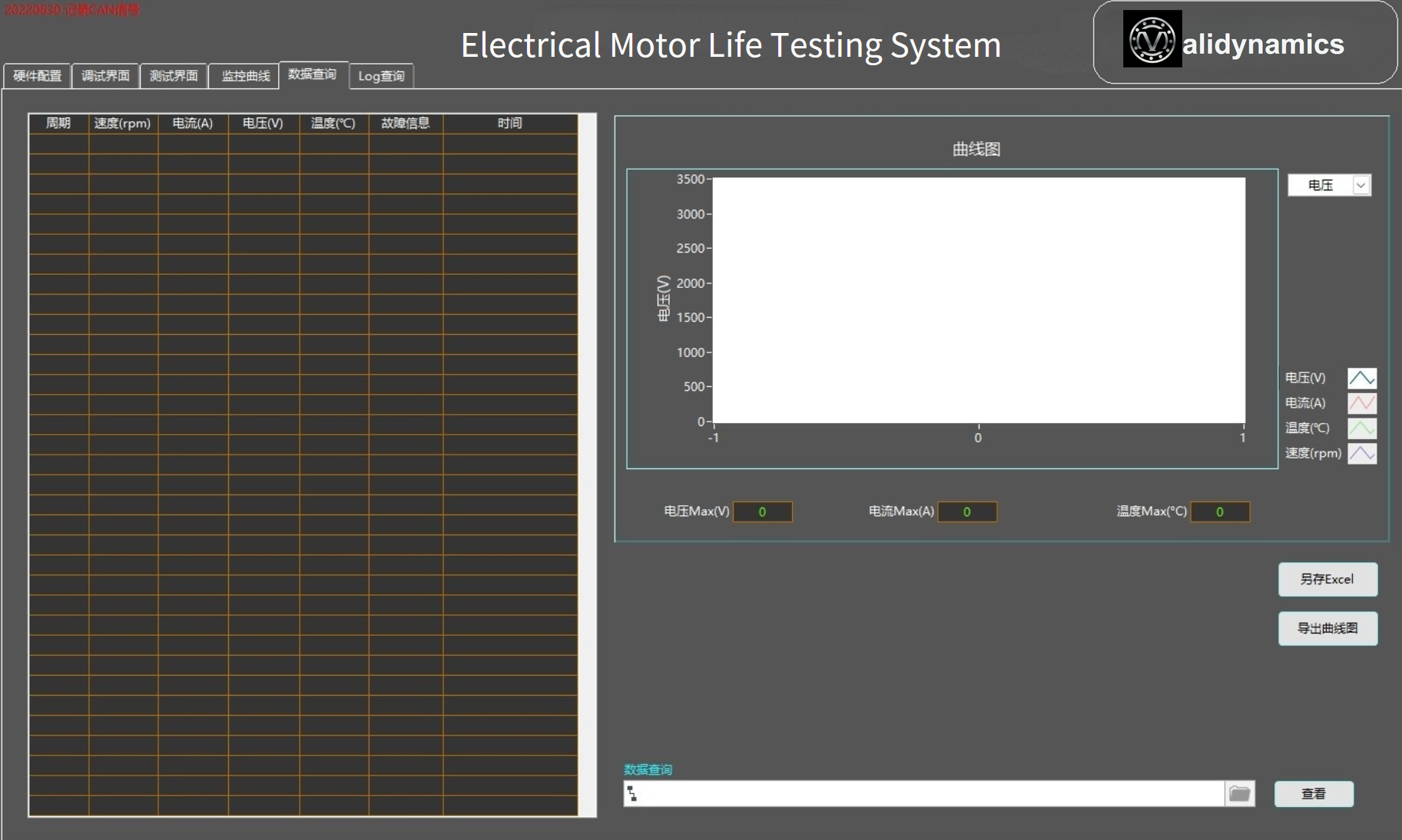
Data Acquisition Interface
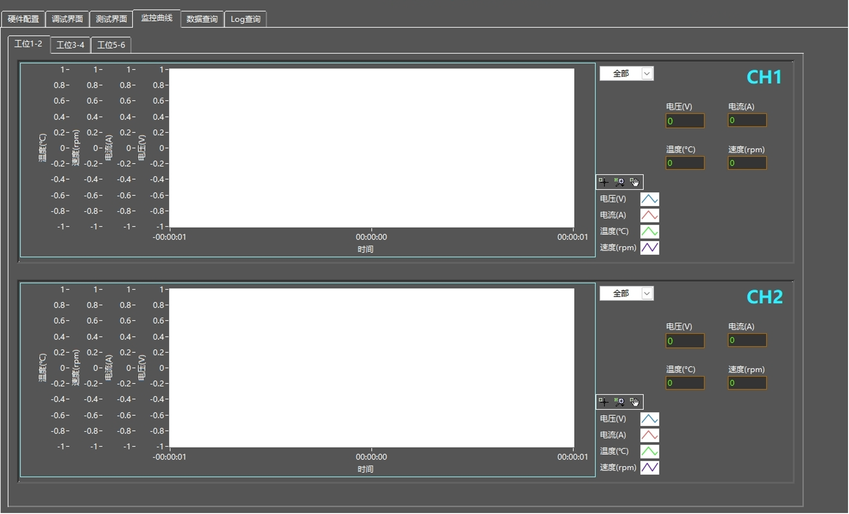
Real Time Curve Monitor
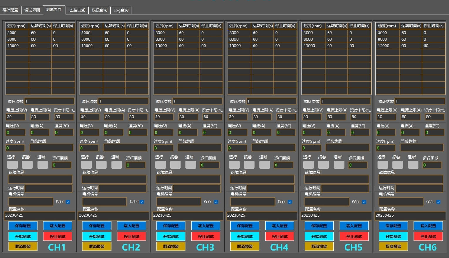
Software Interface
MOTOR-TEST (ATC-1006):
Developed using LABVIEW, it has special testing and graphical plotting features.
The software can calculate and display multiple parameters such as current, torque, speed, etc.
The data is stored and displayed, and it can be easily converted into tables for further analysis.
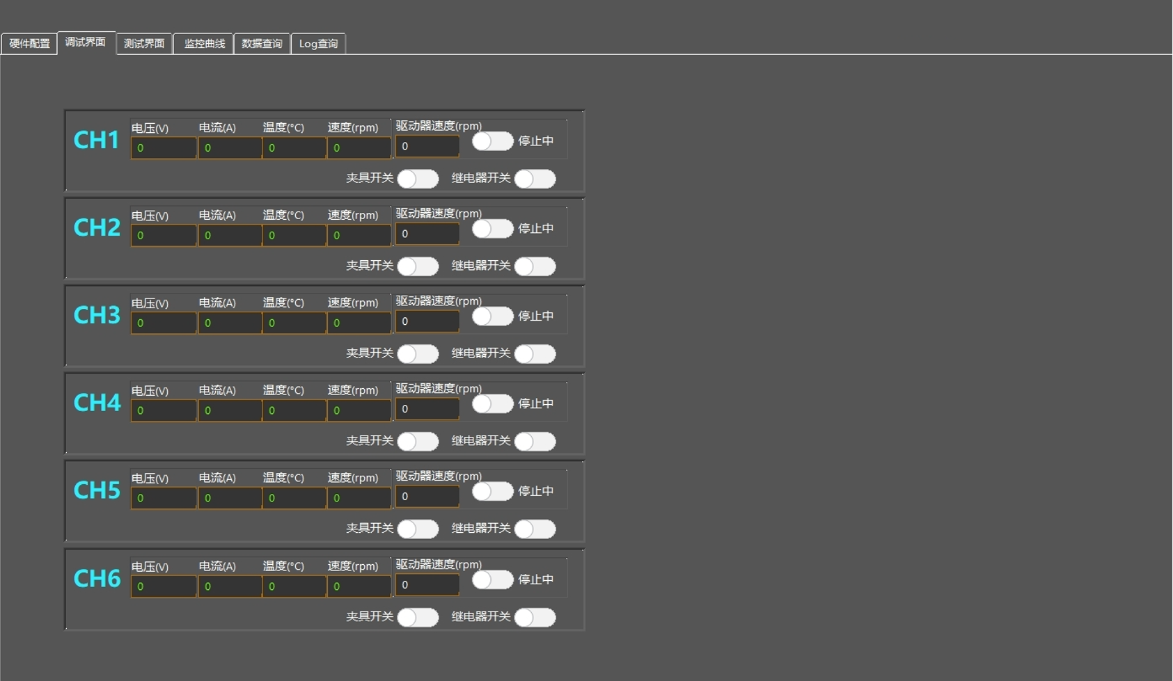
The software provides protection features such as overcurrent and over-temperature protection.
The system can also be customized based on specific client requirements.
This motor lifetime test system helps simulate real-world conditions for motors, allowing for accurate testing and analysis of their performance over time. It is suitable for various applications and industries requiring motor longevity testing, such as automotive, robotics, and other sectors.
Software Interface
Software Interface
Demo / Application Video
Motor testing systems for automation, robot, drone, aviation and medical equipment