From our humble beginnings with a small hysteresis brake, we have grown to make it the core of our flagship products.

The robot joint torque testing primarily involves software installed on an industrial control computer. This software uses an IO card to control relays, which in turn control AC contactors to switch the power supply output to the tested product. Communication ensures that the corresponding voltage is supplied to the product.
During testing, engineers use their software to control the robot joint’s movement. Once the movement is complete, engineers use the testing software to control a load controller, applying a load to the product using a dynamometer. Meanwhile, electrical parameters such as voltage, current, input power, and the torque, speed, output power, and direction of the product are measured. Efficiency is then calculated based on these readings.
Additionally, the angle sensor signals can be read to test the repeatability and positioning accuracy of the robot joint under varying loads. The system supports a wide range of tests, including efficiency testing (gearbox), torsional stiffness testing, backlash testing, start-stop torque testing, no-load friction testing, and drive accuracy testing.

Joint Testing Principle
As shown in above, the equipment primarily consists of an industrial control computer, power analyzer, angle encoder (optional), and high-speed DAQ. The power analyzer is used to measure electrical parameters, including the voltage, current, and power at the driver input, as well as the output voltage (UVW), current (UVW), and the torque and speed signals from the torque-speed sensor.
The angle signal can be read using an angle encoder paired with a decoder. For dynamic measurements, an incremental encoder is required, while an absolute encoder offers higher precision for static measurements.

Test Items
Load Testing:
Function Description:
When a motor drive system operates with a real load, the torque it experiences is not constant. To simulate real-world operating conditions, torque is applied to the motor under test to replicate this variation.
Test Objective:
The purpose of the test is to determine whether parameters such as the motor’s voltage, current, speed, output power, power factor, and efficiency stay within the design specifications under different load conditions.
Test Method:
A dynamometer is used to apply load to the motor, measuring parameters like torque and speed while also testing electrical parameters.
Torque-Speed Characteristics:
The torque-speed curve is automatically tested and plotted through industrial control software. Measurement of the drive motor, driver, and system efficiency primarily relies on a high-precision power analyzer and dynamometer. The industrial control software automatically conducts the measurement and generates a report. The specific measurement methods and standards are outlined as follows:
Constant Speed or Constant Torque Testing
Test Objective:
The goal of this test is to load the motor at specified speed or torque points and observe its performance under these conditions.
Test Method:
A dynamometer is used as the load for the motor under test, ensuring the motor operates in a heated state. The DC bus voltage of the motor controller is set to the rated voltage, and the maximum working current is specified. During the test, the dynamometer software loads according to the set speed or torque points, adjusting the optimal PID values and automatically applying the load in steps, generating the characteristic curve based on user settings.
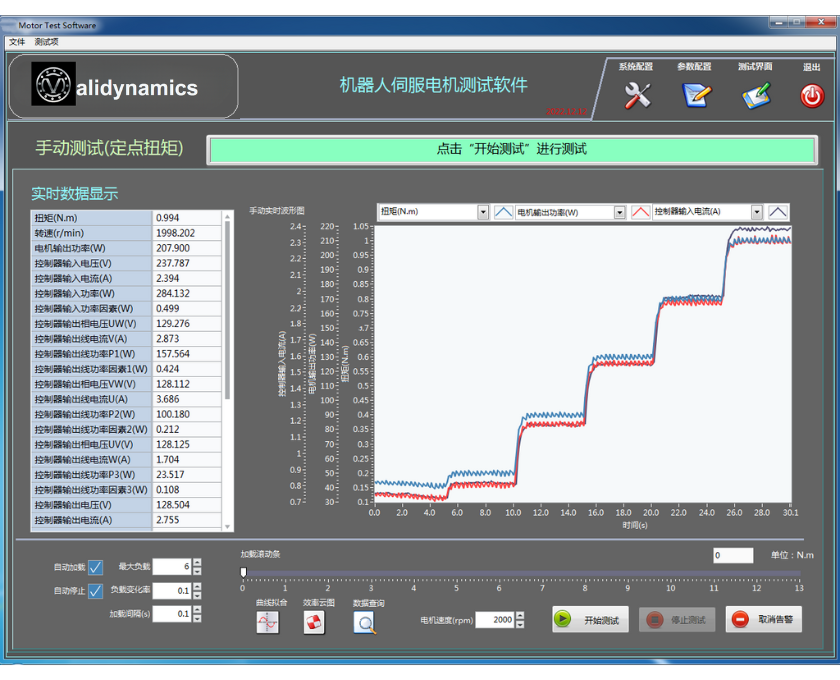
Manual Load Testing
Manual loading significantly reduces PID adjustment time during closed-loop loading. By using open-loop loading, this method allows for manual testing, enabling dynamic loading of arbitrary load waveforms. It provides users with a true simulation of the motor’s real operating conditions.
Stall Testing
Stall testing can be performed using mechanical stalling methods to measure the motor’s performance under lock conditions.
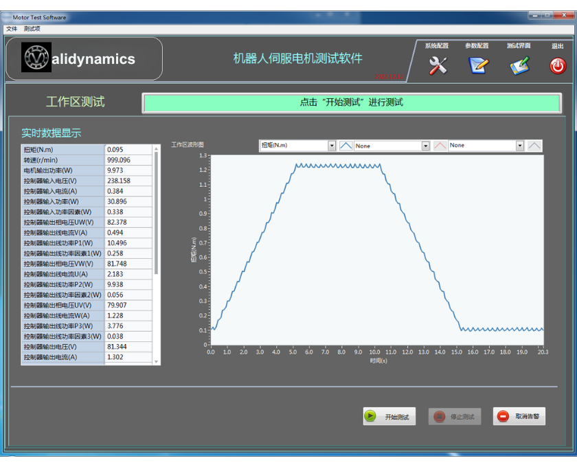
Operating Range Testing
Operating range testing focuses on both rated and peak testing of the motor. It tests the motor’s performance in both short-duration and continuous operation, measuring parameters like torque, speed, power, and temperature. The operating range is represented as a two-dimensional coordinate system with speed and torque. The continuous operating range is defined by the motor’s temperature rise not exceeding the specified value and its ability to work continuously.
In the diagram, the area within “continuous stall torque,” “rated torque,” and “maximum allowable speed” (unshaded region) represents the continuous operating zone, which is limited by motor heat, centrifugal forces, and the limits of commutation or the drive system. The area outside of this range, where the motor can operate at short-term overload, is called the intermittent operating zone (shaded region in the diagram).
Notes:
Workspace Short-Term Curve Graph
Test Method: Based on National Standard GB/T 30549-2014
Continuous Operating Range Test (Defined by National Standard)
The motor under test is fixed onto the test stand, and the testing environment should be unaffected by external radiation or airflow. The test will take place at three points: n0, nN, and nmax.
At these three points, the corresponding maximum load torque will be applied, ensuring the motor’s temperature rise does not exceed the specified design limit.
Continuous Operating Range Test Method:
Short-Term Operating Range Test (Defined by National Standard)
The motor under test is fixed onto the test stand, and the testing environment should be unaffected by external radiation or airflow. This test will take place at the speed points n0 and nmax, applying the rated torque at the specified multiples. The temperature rise must comply with the design specifications within the given time.
Short-Term Operating Range Test Method:
Measurement Parameters:
Key Parameters Defined in the Test:
Back EMF (Electromotive Force) Testing
National Standard Definition:
As per GB/T 30549-2014, the method for testing the back electromotive force constant is defined. The motor under test is not powered, and the tested motor is dragged to a specified speed n by a driving motor. The waveform is observed using an oscilloscope, which must meet the technical requirements. Measure the back EMF at speed n and calculate the back EMF constant using the formula.
Test Method:
Test Parameters:
Note:
Using the integrated power analyzer, line back EMF waveforms can be measured (oscilloscopes can measure reverse back EMF waveforms).

National Standard Definition:
According to the national standard GB/T 21418-2008, the motor’s speed fluctuation test method is defined. The test is conducted under no-load conditions, where the system inputs the rated forward and reverse speed commands (changing direction but not altering the variable values). The average forward and reverse speeds of the motor, denoted as Nccw (counterclockwise) and Ncw (clockwise), are measured. The speed difference between the forward and reverse directions is then calculated according to the formula.
The system runs at rated speed under no-load conditions, and the maximum and minimum transient speeds of the motor are measured. The fluctuation coefficient of speed is calculated based on these values. The maximum transient speed is denoted as Nmax, and the minimum transient speed is denoted as Nmin.

Torque Fluctuation Test
Test Objective: To determine if the torque fluctuation of the motor under test is within the design range. The test results are for reference only.
Test Method:
The load motor is controlled to run at a specified speed while simultaneously driving the motor under test to operate at this speed with load. During one operational cycle, real-time torque data is collected. The torque fluctuation coefficient is then calculated using the obtained torque data and relevant formulas.
Measured Parameters:
National Standard Definition:
According to the national standard GB/T 35089-2018, the load and transmission efficiency test method is defined. The test environment temperature should be (23 ± 5)℃. The efficiency test is conducted when the motor reaches thermal equilibrium under rated torque, with the motor casing temperature ≤ 60℃.
Load Test Method:
At different speeds, the motor is loaded from zero to rated torque. Input/output torque and input/output speed are recorded. For each speed, at least five sets of data are collected. Transmission efficiency is then calculated based on the recorded data, and a torque-efficiency curve for different speeds is plotted.
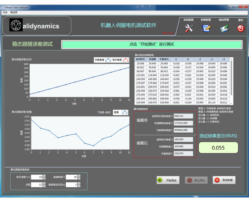
When testing the transmission accuracy of joint motors in static conditions, the load motor is unloaded. The test software controls the rotation of the joint motor by reading the encoder values of the motor in a closed-loop system. Simultaneously, the software collects high-speed feedback from the encoder and compares it with the angle signal from the external angle sensor on the test bench. A curve is then plotted based on this comparison.
The calculated values are used by the system to determine whether the test product meets the required standards. For example, when a fixed angle value (e.g., 10 degrees) is input to the joint motor controller, the output encoder’s angle is read for closed-loop control. The system compares the encoder value with the angle sensor value, calculates the difference, and after a set time interval (e.g., 50ms), the motor is rotated further to obtain the joint’s rotational accuracy.
By rotating the input side one full turn, the system determines both the clockwise and counterclockwise accuracy values, calculates the backlash, and ultimately generates three charts: one for the joint motor’s clockwise rotation accuracy, one for counterclockwise rotation, and one for the backlash.

Position Accuracy Test
For testing the joint motor’s transmission accuracy in static conditions, the test software reads the encoder values of the motor and controls its rotation in a closed-loop system to rotate the joint motor through one or more angles, followed by a pause. During this pause, the external angle sensor records the current angle, then the motor returns to its original position, and the original position’s angle is also recorded. This process repeats, and the recorded values are used to calculate position accuracy and repeatability using a specific formula.
The test system offers users the flexibility to choose between load and no-load options, with the load size being adjustable. Additionally, the system allows for the following customizable settings:
The test is performed through a software interface, which also includes a protection function testing interface.
Belows are different testing interface for your reference. Please contact if you are interested for more details:


Application of hysteresis brake for simple motor test.